


OceanBase Database adopts a shared-nothing distributed cluster architecture, where all nodes are equal. Each node has its own SQL engine, storage engine, and transaction engine, and runs on a cluster of ordinary PC servers. This architecture offers high scalability, high availability, high performance, cost-effectiveness, and strong compatibility with mainstream databases. For more information about the deployment architectures of OceanBase Database, see System architecture.
OceanBase Database uses commodity server hardware and relies on local storage. In a distributed deployment, the servers are also equal to each other without special hardware requirements. The distributed processing in OceanBase Database is built on the shared-nothing architecture. The SQL execution engine within the database has distributed execution capabilities.
OceanBase Database runs a single-process program named observer on each server as the runtime instance of the database. The program uses local files to store data and transaction redo logs.
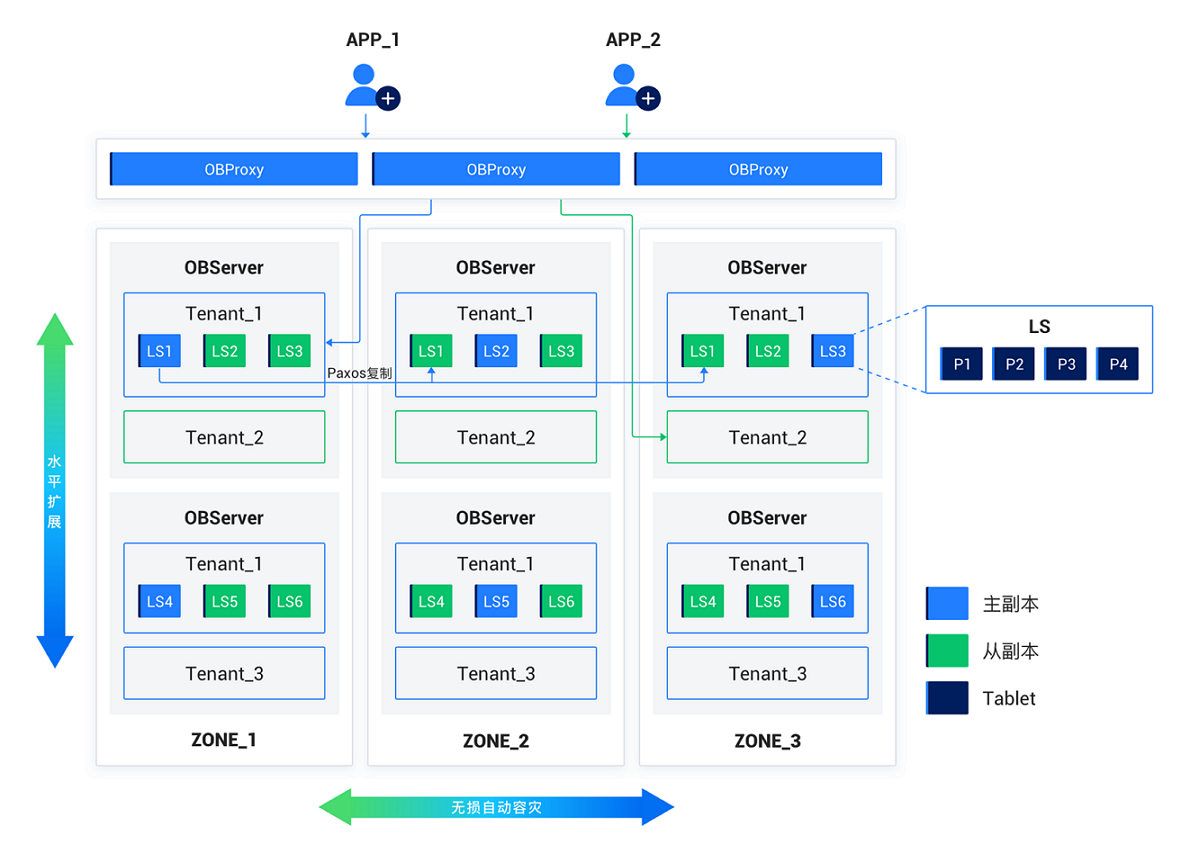
When you deploy an OceanBase cluster, you must configure availability zones (Zones). Each zone consists of multiple servers. A zone is a logical concept that represents a group of nodes that share similar hardware availability in the cluster. Its meaning varies depending on the deployment mode. For example, in a scenario where the cluster is deployed in one IDC, nodes in a zone may belong to the same rack or the same switch. If the cluster is deployed across IDCs, each zone can correspond to one IDC.
You can store multiple replicas of user data within the distributed cluster for disaster recovery and pressure relief. A zone contains only one replica of data for the same tenant, but multiple replicas of the same data can be stored in different zones. The Paxos protocol ensures data consistency among replicas.
OceanBase Database has the multi-tenant feature built in. Each tenant has its own database instance. You can set the distributed deployment mode of a tenant at the tenant level.
The components of collaboration in an OceanBase database instance from the underlying layer to the upper layer are the multi-tenant layer, storage layer, replication layer, load balancing layer, transaction layer, SQL layer, and access layer.
Multi-tenant layer
To simplify the management of multiple business databases deployed on a large scale and reduce resource costs, OceanBase Database offers the unique multi-tenant feature. In an OceanBase cluster, you can create many isolated "instances" of databases, which are called tenants. From the perspective of applications, each tenant is a separate database. In addition, each tenant can be configured for MySQL or Oracle compatibility. After your application is connected to a MySQL-compatible tenant, you can create users and databases in the tenant. The user experience is similar to that with a standalone MySQL database. In the same way, after your application is connected to an Oracle-compatible tenant, you can create schemas and manage roles in the tenant. The user experience is similar to that with a standalone Oracle database. After a new cluster is initialized, a tenant named sys is created. The sys tenant is a MySQL-compatible tenant that stores the metadata of the cluster.
To isolate the resources of different tenants, each observer process can have multiple virtual containers belonging to different tenants. These containers are called resource units (UNIT). The resource units of each tenant across multiple nodes form a resource pool. The resource units include CPU and memory resources.
Storage layer
The storage layer provides data storage and access on a table or partition basis. Each partition corresponds to a tablet (shard), and a non-partitioned table corresponds to a tablet.
The internal structure of a tablet is a layered storage structure with four layers: MemTable, L0-level mini SSTable, L1-level minor SSTable, and major SSTable. DML operations such as inserts, updates, and deletions write data to the MemTable first. When the MemTable reaches a specified size, the data in the MemTable is flushed to the disk to become an L0-level mini SSTable. If the number of L0-level mini SSTables reaches the threshold, multiple L0-level mini SSTables are merged into an L1-level minor SSTable. During off-peak hours of a day, the system merges all MemTables, L0-level mini SSTables, and L1-level minor SSTables into a major SSTable.
Each SSTable consists of several fixed-size macroblocks, each of which contains multiple variable-size microblocks.
The microblocks of a major SSTable are encoded during the merge process. The data in the microblocks is encoded by column, and then compressed. The compression rules include dictionary, run-length, constant, and differential encoding. After each column is compressed, the columns are encoded by using equal value or substring matching rules. This encoding can significantly reduce the size of data and accelerate future queries by refining the features of data in columns.
After the data is encoded, a lossless compression algorithm can be specified as needed to further reduce the data size.
Replication layer
The replication layer uses log streams (LS, Log Stream) to synchronize the status among replicas. Each tablet corresponds to a specific log stream, and multiple tablets can correspond to one log stream. The redo logs generated by DML operations written to tablets are persisted in the corresponding log streams. Multiple replicas of a log stream are distributed across different availability zones, and a consensus algorithm is maintained among the replicas. One of the replicas is elected as the leader, and the other replicas serve as followers. DML operations and strong-consistency queries are performed only on the leader.
Generally, each tenant has only one leader on each server, but can have multiple followers. The total number of log streams of a tenant depends on the configurations of the primary zone and locality.
Log streams use an improved Paxos protocol to persist redo logs on the local server and send the redo logs over the network to followers. After receiving the redo logs, followers persist the logs and send an acknowledgment back to the leader. The leader confirms that the redo logs are persisted successfully after a majority of followers persist the logs successfully. Followers use the redo logs for real-time replay to keep their states consistent with the leader.
The leader of a log stream becomes the leader after it is elected. A normally working leader continuously extends its lease within the lease period through the election protocol. The leader performs only the duties of a leader with a valid lease. The lease mechanism ensures the robustness of exception handling of the database.
The replication layer automatically responds to server failures to ensure the continuous availability of the database. If less than half of the servers hosting followers crash, namely, more than half of the replicas are still working, the database services are not affected. If a server hosting the leader crashes, its lease cannot be extended. After the lease expires, other followers will elect a new leader and grant a new lease to the new leader. Then, the database services can be restored.
Equilibration layer
When you create a table or a partition, the system selects appropriate log streams to create tablets based on the equilibration principle. If the attributes of the tenant change, new machine resources are added, or tablets are unevenly distributed across servers after a long period of use, the equilibration layer will equilibrate data and services across servers by splitting and merging log streams and moving log stream replicas during the process.
When the tenant expands and more server resources are available, the equilibration layer will split the existing log streams and select an appropriate number of tablets to split into new log streams, and then migrate the new log streams to the new servers to make full use of the expanded resources. When the tenant shrinks and some servers are idle, the equilibration layer will migrate the log streams from the idle servers to other servers and merge them with the log streams on the other servers to reduce the resource usage of the servers.
With the long-term use of the database, tables are created or deleted and more data is written. Even if the number of server resources remains unchanged, the original equilibrium may be destroyed. A common scenario is that after a batch of tables is deleted, the number of tablets on the servers where the tables were originally clustered decreases. The tablets on other servers need to be evenly distributed to these servers. The equilibration layer will generate an equilibration plan on a regular basis. It splits log streams on servers with many tablets into temporary log streams, carrying the tablets to be moved. The temporary log streams are merged with the log streams on the destination servers. This process achieves equilibrium.
Transaction layer
The transaction layer ensures the atomicity of DML operations in a single log stream or multiple log streams and the multiversion isolation between concurrent transactions.
Atomicity
The write-ahead logs of a log stream ensure the atomicity of transactions modifying multiple tablets. When a transaction modifies multiple log streams, write-ahead logs are generated and persisted in each log stream. The transaction layer ensures the atomicity of the transaction through an optimized two-phase commit protocol.
When a transaction that modifies multiple log streams initiates a commit, it selects one of the log streams as the coordinator. The coordinator communicates with all log streams modified by the transaction to check whether the write-ahead logs are persisted. After all log streams complete persistence, the transaction is in the commit state. Then, the coordinator drives all log streams to write the commit log of the transaction, indicating the final commit status of the transaction. During log replay or after the database is restarted, the status of a transaction is determined based on the commit log.
In the case of a database restart after a crash, if a transaction is not committed before the crash, its write-ahead log may be completed but its commit log may not be written. Each log stream has a write-ahead log that contains the list of all transaction logs in the stream. Based on this information, the coordinator can be re-determined and its state can be restored, and then the two-phase commit protocol can be resumed to commit or abort the transaction.
Isolation
The Global Timestamp Service (GTS) is a service that generates continuous and increasing timestamps in the tenant. It ensures the availability of timestamps through multi-replica deployment. The mechanism is the same as the log stream replica synchronization mechanism described in the preceding Replication layer section.
Each transaction obtains a timestamp from the GTS as the commit version number for the transaction when the transaction is committed, and the timestamp is persisted in the write-ahead log of the log stream. Data modified in the transaction is marked with the commit version number.
Each statement (for the Read Committed isolation level) or transaction (for the Repeatable Read and Serializable isolation levels) begins with a timestamp request from the GTS as the read version number. When data is read, data of the version earlier and closest to the read version number is chosen. This process provides a unified global snapshot of data for read operations.
SQL layer
The SQL layer converts an SQL request into data access requests for one or more tablets.
SQL layer components
The execution process of an SQL request is as follows: parser, resolver, transformer, optimizer, code generator, and executor.
The parser is responsible for lexical or syntactic parsing. It breaks down the user's SQL statement into individual "tokens" and then parses the entire request based on the predefined syntax rules, generating a syntax tree (Syntax Tree).
The resolver is responsible for semantic parsing. Based on the database metadata, it translates the tokens in SQL requests into corresponding objects (such as databases, tables, columns, and indexes). The data structure generated by this process is called the statement tree.
The transformer is responsible for logical rewriting. Based on internal rules or a cost model, it rewrites an SQL query statement into an equivalent one and provides it to the subsequent optimizer for further optimization.
A transformer performs equivalent transformations on the original statement tree to generate a new statement tree.
The optimizer (optimizer) generates the best execution plan for SQL requests. To generate an execution plan, the optimizer needs to consider multiple factors, including the semantics of the SQL request, the data characteristics of the objects involved, and the physical distribution of the objects, to resolve issues such as access path selection, join order, join algorithm selection, and distributed plan generation.
The code generator (CG) generates executable code from execution plans without making any optimization choices.
The executor (executor) starts the execution process of an SQL query.
In addition to the standard SQL process, the SQL layer has the Plan Cache feature to cache historical execution plans in memory. This way, the system can reuse the plans for subsequent executions, avoiding the need to optimize the queries repeatedly. In conjunction with the Fast-parser module, the system can directly parameterize a text string through lexical analysis and then cache the parameterized text and constant parameters in the Plan Cache. This allows an SQL query to directly hit the Plan Cache during frequent execution, accelerating the processing of the SQL query.
Multiple plans
Execution plans at the SQL layer are classified into local, remote, and distributed plans. A local plan accesses only data on the local server. A remote plan accesses only data on a remote server. A distributed plan accesses data on more than one server. The execution plan is divided into multiple subplans for execution on multiple servers.
The SQL layer supports parallel execution, which decomposes an execution plan into multiple parts for processing by multiple execution threads through scheduling. This way, the execution plan can be parallelized. Parallel execution makes full use of the CPU and I/O resources of the server to shorten the response time of individual queries. You can apply parallel queries to distributed execution plans as well as local execution plans.
Access layer
OceanBase Database Proxy (ODP), also known as OBProxy, is the access layer of OceanBase Database. It forwards user requests to an appropriate OceanBase instance for processing.
ODP is an independent process that is deployed separately from an OceanBase database instance. ODP listens on a network port and supports direct connection from applications that use the MySQL driver. It is compatible with the network protocols of MySQL.
ODP can automatically discover the tenants and data distribution of an OceanBase cluster. For each SQL statement proxied, ODP can identify the data to be accessed by the statement and forward it directly to the OceanBase Database instance where the data is located.
ODP can be deployed on each application server that needs to access the database or on the server where OceanBase Database resides. If ODP is deployed on each application server, the application directly connects to the ODP on the same server. All requests are forwarded by ODP to an appropriate OceanBase Database server. If ODP is deployed on the server where OceanBase Database resides, the network load balancing service needs to be used to aggregate multiple ODPs into one entry address for application access.