


Overview
OceanBase Database supports two deployment modes: Shared-Nothing (SN) and Shared-Storage (SS).
Shared-Nothing mode
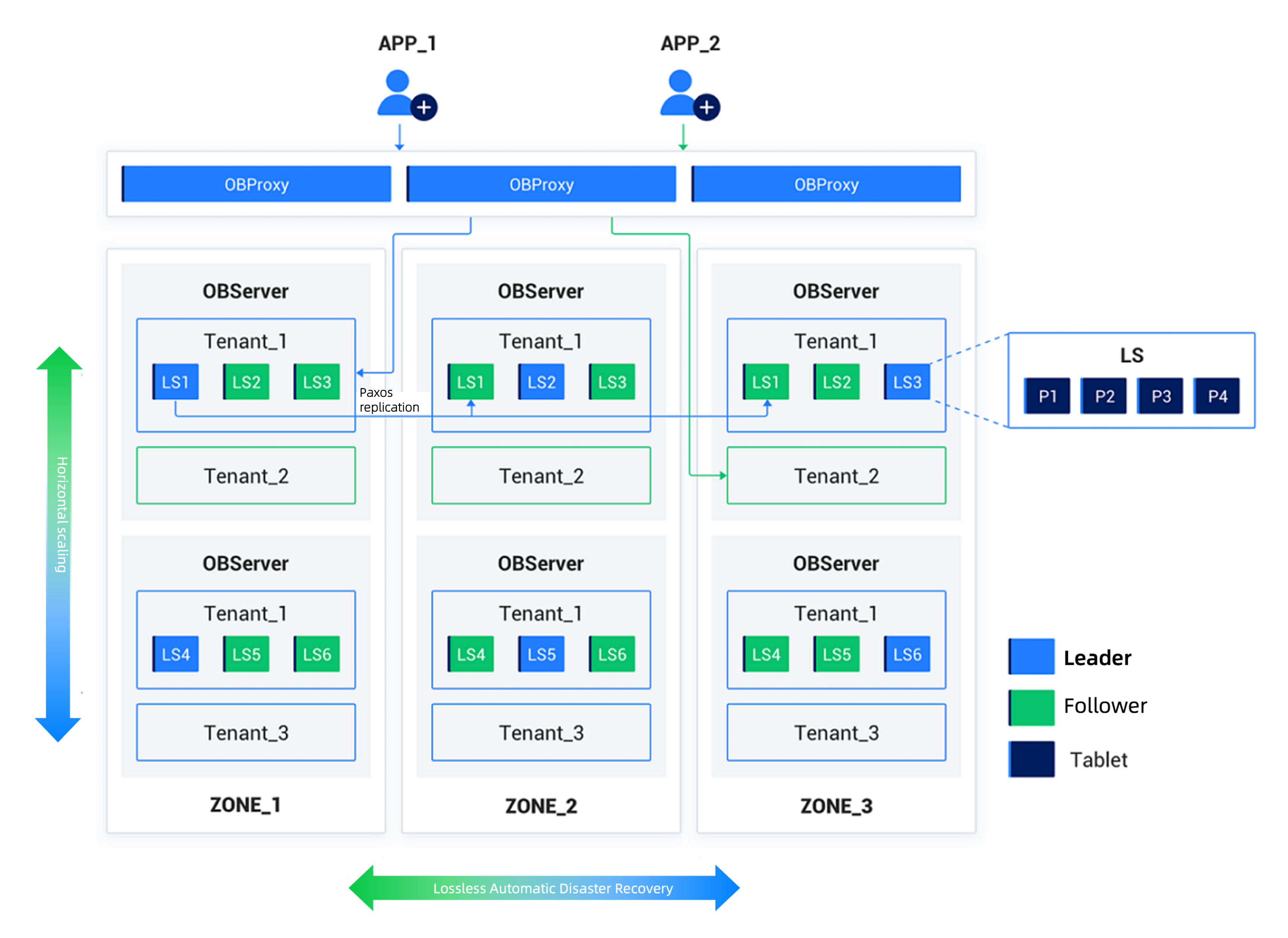
In the Shared-Nothing (SN) mode, nodes are completely equal to each other. Each node has its own SQL engine, storage engine, and transaction engine. The nodes run on a cluster of general-purpose PC servers. This mode offers high scalability, high availability, high performance, low cost, and high compatibility with mainstream databases.
OceanBase Database uses general-purpose server hardware and relies on local storage. In a distributed deployment, multiple servers are used, and they are equal to each other without special hardware requirements. OceanBase Database uses the Shared Nothing architecture for distributed database processing. The SQL execution engine in OceanBase Database has distributed execution capabilities.
On each server of OceanBase Database, a single-process program named observer runs as the database instance. It uses local files to store data and transaction redo logs.
To deploy an OceanBase cluster, you need to configure zones. Each zone consists of several servers. A zone is a logical concept that represents a group of nodes with similar hardware availability within the cluster. The meaning of a zone varies depending on the deployment mode. For example, if the entire cluster is deployed in a single data center (IDC), the nodes in a zone can be on the same rack or connected to the same switch. If the cluster is distributed across multiple data centers, each zone can correspond to a data center.
In a distributed cluster, user data can be stored in multiple replicas for fault tolerance and load balancing. A single replica of the data exists within a zone, and multiple replicas can be stored across different zones. Paxos protocol ensures data consistency between replicas.
OceanBase Database supports the multi-tenant feature. Each tenant is an independent database instance. You can set the data distribution strategy, replica type, and number of replicas for a tenant at the tenant level. Resources such as CPU, memory, and I/O are isolated between tenants.
Shared-Storage mode
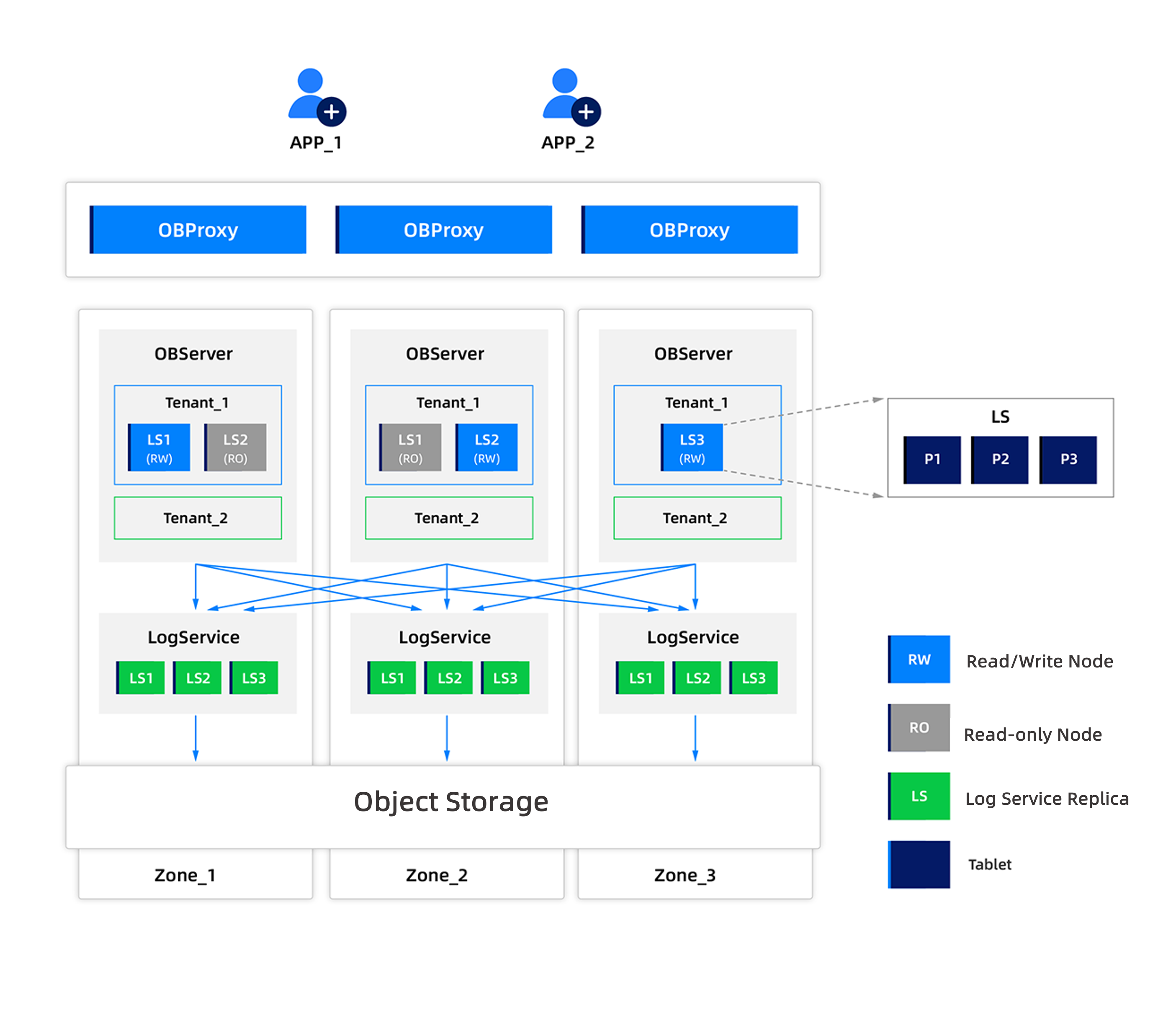
In the Shared-Storage (SS) mode, the system adopts a storage-compute separation architecture. Each tenant stores its data and logs on the shared object storage. Each tenant caches hot data and logs on the local storage of each node.
For more information about the deployment architecture of OceanBase Database, see System architecture.
The database instance of an OceanBase cluster consists of different components that work together. From bottom to top, the components are the multi-tenant layer, storage layer, replication layer, balancing layer, transaction layer, SQL layer, and access layer.
Multi-tenant layer
To simplify the management of multiple business databases and reduce resource costs, OceanBase Database provides the multi-tenant feature. In an OceanBase cluster, you can create many isolated database instances, called tenants. From the perspective of applications, each tenant is equivalent to an independent database instance. Moreover, each tenant can choose between MySQL and Oracle compatible modes. After connecting to a MySQL-compatible tenant, an application can create users and databases within the tenant, achieving the same experience as using an independent MySQL database. Similarly, after connecting to an Oracle-compatible tenant, an application can create schemas and manage roles within the tenant, achieving the same experience as using an independent Oracle database. After a new cluster is initialized, a special tenant named sys, called the system tenant, exists by default. The system tenant stores the metadata of the cluster and operates in MySQL compatible mode.
To isolate resources between tenants, each observer process can have multiple virtual containers belonging to different tenants, called resource units (UNIT). Resource units include CPU and memory resources. The resource units of a tenant across multiple nodes form a resource pool.
Storage layer
The storage layer provides data storage and access at the granularity of a table or a partition. Each partition corresponds to a tablet (shard) for storing data. A non-partitioned table defined by a user also corresponds to a tablet.
The internal structure of a tablet is hierarchical, consisting of four layers: MemTable, L0-level Mini SSTable, L1-level Minor SSTable, and Major SSTable. DML operations such as insert, update, and delete first write data to the MemTable. When the MemTable reaches a certain size, it is flushed to disk as an L0-level Mini SSTable. When the number of L0-level Mini SSTables reaches a threshold, they are merged into an L1-level Minor SSTable. During the off-peak hours of the business day, the system merges all MemTables, L0-level Mini SSTables, and L1-level Minor SSTables into a Major SSTable.
Each SSTable consists of several fixed-size macroblocks of 2 MB. Each macroblock contains multiple variable-length microblocks.
During the merge process, microblocks in the Major SSTable are encoded to convert their format. Data within each microblock is encoded column-wise using rules such as dictionary, run-length, constant, or difference encoding. After compression, multi-column encoding is performed using rules such as equality or substring matching. Encoding significantly compresses data and accelerates subsequent queries by extracting column-specific features.
After encoding compression, you can further compress the data using a lossless compression algorithm specified by the user to improve the compression ratio.
Replication layer
Shared-nothing mode
In the shared-nothing (SN) mode, the replication layer synchronizes the state between multiple replicas using log streams (LS). Each tablet corresponds to a specific log stream, and each log stream can be associated with multiple tablets. DML operations on a tablet generate redo logs that are persisted in the log stream. The log stream has multiple replicas distributed across different zones. A consensus algorithm ensures that one replica is elected as the leader, and the others are followers. DML operations and strongly consistent queries on a tablet are only executed on the leader replica of its corresponding log stream.
Typically, each tenant has only one leader replica of a log stream on each server, and may have multiple follower replicas of other log streams. The total number of log streams for a tenant depends on the configuration of primary zones and locality.
The log stream uses an improved Paxos protocol to persist redo logs on the server and send them to the follower replicas. After each follower replica completes its persistence, it responds to the leader replica. The leader replica confirms the persistence of the redo logs only after a majority of replicas have successfully persisted them. Follower replicas replay the redo logs in real-time to ensure their state remains consistent with the leader replica.
When a leader replica is elected, it obtains a lease. A normally functioning leader replica extends its lease through the election protocol while the lease is valid. The leader replica only performs its duties while the lease is valid. The lease mechanism ensures the database's ability to handle exceptions.
The replication layer automatically handles server failures to ensure continuous database availability. If fewer than half of the server replicas hosting follower replicas fail, more than half of the replicas are still functioning, so the database service remains unaffected. If the server hosting the leader replica fails, its lease cannot be extended. Once the lease expires, other follower replicas will elect a new leader and obtain a new lease, restoring the database service.
Shared storage mode
Building on the object storage-based shared storage architecture, we further designed a cloud-native database architecture that separates logs (log service) from compute resources (compute nodes, divided into read/write and read-only nodes). In the shared storage (SS) mode, compared to the SN mode, the database's log service is abstracted into a separate, high-performance, highly available, strongly consistent, and optimized distributed storage system tailored for log access characteristics.
In this architecture, log streams (LS) synchronize logs between log service replicas through a consensus protocol to ensure data persistence. The number of log service replicas is decoupled from the number of compute nodes. The number of compute nodes ensures availability, while the number of log service replicas ensures durability under high availability.
When a read/write node (RW) is elected as the leader, it also obtains a lease, consistent with the SN mode. After the election, the RW node uses the Paxos protocol to persist data in multiple replicas of the log service and ensures that a majority of replicas complete the persistence. Read-only nodes (RO) read data from the most recent log service replicas and replay it locally.
The log service automatically handles server failures to ensure continuous database availability. If fewer than half of the log service replicas are hosted on failed servers, more than half of the replicas are still functioning, so the database service remains unaffected, achieving durability under high availability. Additionally, in the SS mode, compute nodes can directly restore and resume operations using the log service and shared object storage without relying on a majority of compute nodes. Redundant compute nodes not only ensure high availability but also provide read/write separation capabilities.
Balancing layer
When creating new tables or adding partitions, the system selects appropriate log streams based on balancing principles to create tablets. When a tenant's properties change, new server resources are added, or tablets become unbalanced after long-term use, the balancing layer performs log stream splits and merges and moves log stream replicas to rebalance data and services across servers.
When a tenant expands and obtains more server resources, the balancing layer splits existing log streams and selects an appropriate number of tablets to split into new log streams. These new log streams are then migrated to the newly added servers to fully utilize the expanded resources. When a tenant reduces its server resources, the balancing layer migrates log streams from the servers being reduced to other servers and merges them with existing log streams on those servers to reduce resource usage.
As the database is used long-term, users continuously create or delete tables and write more data. Even if the number of server resources remains unchanged, the original balanced state may be disrupted. A common scenario is when users delete a batch of tables. If these tables were concentrated on certain servers, the number of tablets on those servers decreases. The balancing layer periodically generates a balancing plan, splits log streams from servers with many tablets into temporary log streams that carry the tablets to be moved, migrates the temporary log streams to the target servers, and merges them with existing log streams on the target servers to achieve balance.
Transaction layer
The transaction layer ensures the atomicity of DML operations on a single log stream and across multiple log streams, and also ensures multi-version isolation between concurrent transactions.
Atomicity
Transactions on a log stream, even involving multiple tablets, can be atomic through the write-ahead log (WAL) of the log stream. When a transaction involves multiple log streams, each log stream generates and persists its own WAL. The transaction layer uses an optimized two-phase commit protocol to ensure the atomicity of the transaction.
When a transaction involving multiple log streams initiates a commit, it selects one log stream as the coordinator. The coordinator communicates with all log streams modified by the transaction to check if their WALs are persisted. Once all log streams complete persistence, the transaction enters the commit state. The coordinator then drives all log streams to write the commit log for the transaction, indicating the final commit status. When a follower replica replays logs or the database restarts, committed transactions are determined by their commit logs.
In a server restart scenario, for transactions that were not completed before the restart, the WAL may have been written but the commit log may not have been written. Each log stream's WAL contains the list of all log streams involved in the transaction. This information can be used to identify the coordinator and restore its state, resuming the two-phase commit protocol until the transaction reaches a final commit or abort state.
Isolation
The Global Timestamp Service (GTS) is a service that generates continuously increasing timestamps within a tenant. It ensures availability through multiple replicas, and its underlying mechanism is consistent with the log stream replica synchronization mechanism described in the replication layer.
When a transaction is committed, it obtains a timestamp from GTS as its commit version number and persists this timestamp in the WAL of the log stream. All data modified within the transaction is marked with this commit version number.
At the start of each statement (for the Read Committed isolation level) or each transaction (for the Repeatable Read and Serializable isolation levels), a timestamp is obtained from GTS as the statement or transaction's read version number. During data reads, the system skips transaction versions greater than the current read version number and selects the largest version number less than the current read version number. This provides a unified global data snapshot for read operations.
SQL layer
The SQL layer translates user SQL requests into data access operations for one or more tablets.
Components of the SQL layer
The execution process of a request in the SQL layer is as follows: Parser, Resolver, Transformer, Optimizer, Code Generator, and Executor. Specifically:
The Parser is responsible for lexical and syntactic analysis. It breaks down the user's SQL statement into individual "tokens" and parses the entire request according to predefined grammar rules, converting it into a syntax tree.
The Resolver is responsible for semantic analysis. It translates the tokens in the SQL request into corresponding database objects (such as databases, tables, columns, and indexes) based on database metadata. The resulting data structure is called a statement tree.
The Transformer is responsible for logical rewriting. It rewrites the SQL statement into an equivalent form based on internal rules or cost models and provides it to the subsequent optimizer for further optimization.
The Transformer works by performing equivalent transformations on the original statement tree, resulting in a new statement tree.
The Optimizer generates the optimal execution plan for the SQL request. It considers multiple factors, including the semantics of the SQL request, the data characteristics of the objects, and their physical distribution, to solve problems such as access path selection, join order selection, join algorithm selection, and distributed plan generation. It ultimately generates the execution plan.
The Code Generator converts the execution plan into executable code without performing any optimization.
The Executor initiates the execution of the SQL statement.
In addition to the standard SQL execution process, the SQL layer has a plan cache feature that stores historical execution plans in memory. Subsequent executions can reuse this plan, avoiding the need for repeated query optimization. Combined with the fast-parser module, which directly parameterizes text strings using lexical analysis, the SQL statement can directly hit the plan cache, accelerating frequently executed SQL statements.
Types of plans
The SQL layer supports three types of execution plans: local, remote, and distributed. A local execution plan accesses data from the local server. A remote execution plan accesses data from a non-local server. A distributed execution plan accesses data from multiple servers and divides the execution plan into multiple subplans to be executed across servers.
The SQL layer's parallel execution capability decomposes the execution plan into multiple parts, which are executed by multiple execution threads. Through a scheduling mechanism, the execution plan is processed in parallel. Parallel execution fully utilizes the CPU and I/O processing capabilities of the server, reducing the response time for individual queries. Parallel query technology can be used for both distributed and local execution plans.
Access layer
OceanBase Database Proxy (ODP), also known as OBProxy, is the access layer of OceanBase Database. It forwards user requests to the appropriate OceanBase Database instance for processing.
ODP is an independent process instance and is deployed separately from OceanBase Database instances. ODP listens on network ports, is compatible with the MySQL network protocol, and supports direct connections to OceanBase Database using MySQL drivers.
ODP can automatically discover tenant and data distribution information in OceanBase clusters. For each SQL statement it proxies, it identifies the data the statement will access and forwards the statement directly to the OceanBase Database instance on the server where the data resides.
ODP can be deployed in two ways: either separately from OBServer nodes (on a dedicated server or on the same server as the application) or on the same server as the OBServer nodes. After deploying ODP, all user requests are forwarded by ODP to the appropriate OceanBase Database server. You can use a network load balancing service to aggregate multiple ODP instances into a single entry point for applications.
For more information about ODP deployment, see ODP official documentation.