Meet OceanBase AI Database, the unified database for operational data, real-time analytics, and AI. Explore ->
Meet OceanBase AI Database, the unified database for operational data, real-time analytics, and AI. Explore ->
RPO and RTO Explained: A Decision Framework for Database DR Architecture

- RTO is not failover time — it is Detection + Decision + Failover + Validation + Reconnection, and the database step is usually the smallest.
- RPO = 0 requires synchronous consensus (Paxos/Raft) within a single cluster; cross-cloud replication is asynchronous and cannot guarantee zero data loss.
- The right architecture is a lookup, not a debate — once you know your RTO/RPO targets and cost tolerance, the decision matrix maps directly to a topology.
RPO and RTO used to be backend planning terms. Today, they are architecture decisions with direct business impact. Uptime Institute’s 2025 analysis found that 54% of organizations said their most recent significant outage cost more than $100,000, and one in five put the loss above $1 million.
Yet many teams still set recovery targets the wrong way. They inherit SLA numbers from contracts or copy them from other systems without grounding them in workload behavior, transaction criticality, dependency chains, and failure domains. The result is predictable: either an overbuilt DR architecture that wastes budget, or an underbuilt one that fails under real incident conditions.
This post explains how to derive RPO and RTO from first principles, where teams miscalculate them, and how to map target recovery objectives to concrete OceanBase architectures.
What RTO and RPO Actually Mean
Recovery Point Objective (RPO) is the maximum amount of data you can afford to lose, measured backward from the moment of failure. An RPO of zero means no transaction can be lost. An RPO of 30 seconds means you accept losing up to 30 seconds of committed writes.
Recovery Time Objective (RTO) is the maximum duration your system can be unavailable after a failure, measured from the moment the failure occurs to the moment the application is serving traffic again.
Both are upper bounds, not averages. Your DR architecture must meet them in the worst case, not just the common case.
Key distinction: RPO is about data. RTO is about service. A system can have RPO = 0 (no data lost) but RTO = 10 minutes (the application is down while failover completes). Conflating the two leads to architectures that solve the wrong problem.
These metrics bridge disaster recovery (the technical mechanics of restoring systems) and business continuity (can the organization keep operating while those mechanics execute). RPO and RTO are where both concerns converge into measurable targets.
How to Calculate Your RTO Requirement
RTO is not a single operation. It is a chain of sequential steps, and the total is the sum:
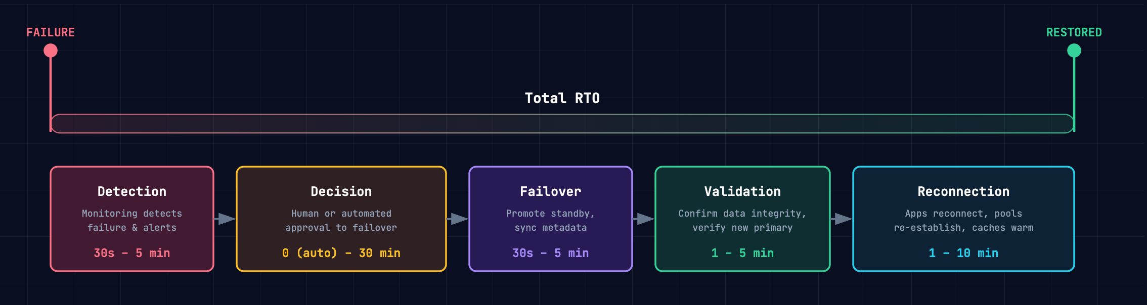
| Component | What it covers | Typical range |
| Detection | Monitoring detects the failure and alerts the team (or automation) | 30 seconds – 5 minutes |
| Decision | Human or automated decision to initiate failover | 0 (automated) – 30 minutes (manual approval) |
| Failover | Database promotes standby to primary, syncs metadata | 30 seconds – 5 minutes |
| Validation | Confirm data integrity, verify the new primary is serving correctly | 1 – 5 minutes |
| Reconnection | Applications reconnect, connection pools re-establish, caches warm | 1 – 10 minutes |
A database that fails over in 30 seconds still produces a 12-minute RTO if detection takes 2 minutes, the on-call engineer takes 5 minutes to approve, and the application takes another 5 minutes to reconnect.
The practical question: For each workload, what is the actual cost per minute of downtime? Multiply that by your RTO components, and you have the business case for automating each step versus leaving it manual.
How to Calculate Your RPO Requirement
RPO is determined by one architectural choice: how data is replicated before a failure occurs.
| Replication method | RPO | How it works |
| Synchronous (Paxos/Raft consensus) | 0 | A transaction is not acknowledged until a majority of replicas confirm the write. No committed data can be lost. |
| Asynchronous with direct sync | Near-zero (milliseconds of lag) | The standby streams redo logs from the primary in real time, but the primary does not wait for standby acknowledgment. Under normal conditions, lag is milliseconds — but during network partitions or load spikes, lag can grow. |
| Asynchronous with log archiving | Seconds to minutes | Logs are written to object storage and pulled by the standby on a delay. Simpler and cheaper, but the gap between primary and standby is structurally larger. |
The nuance that matters:
- Within a single OceanBase cluster, Paxos consensus delivers RPO = 0 — every committed transaction is replicated to a majority before acknowledgment.
- Cross-cloud physical standby replication is asynchronous: millisecond lag under normal conditions, but not zero. Be honest about this distinction when setting targets.
The practical question: What is the cost of losing the last N seconds of transactions? For a payment system, even one lost transaction may be unacceptable. For an internal reporting pipeline, losing 30 seconds during a regional failure may be perfectly fine.
The Decision Matrix: Mapping RTO/RPO to Architecture
Once you have your RTO and RPO requirements, the architecture selection becomes a lookup — not a subjective debate. The tighter your targets, the more you invest in replication, network infrastructure, and operational automation. The tables below make that cost-recovery trade-off explicit.
OceanBase provides two layers of protection — intra-cluster multi-replica consensus and cross-cloud DR — and you can combine them.
Intra-Cluster Topologies (Paxos Consensus)
These architectures use synchronous Paxos replication within a single OceanBase cluster. Every committed transaction is replicated to a majority of replicas before acknowledgment, delivering RPO = 0 by design.
| Topology | Failure tolerance | RPO | RTO | Trade-off |
| 3 IDCs, same region (3 replicas) | Any 1 IDC | 0 | < 8 s | Cannot survive city-level failure |
| 3 IDCs, same region + arbitration | Any 1 IDC | 0 | < 8 s | 2 full replicas + 1 arb; lower cost than 3 full replicas |
| 5 IDCs, 3 regions (5 replicas) | Any 1 city or any 2 IDCs | 0 | < 8 s | Cross-region latency on writes; requires 3 cities |
| 3 IDCs, 2 regions + arbitration | Any 1 IDC in primary city | 0 | < 8 s | Cannot survive primary-city failure; lowest cross-region cost |
| 5 IDCs, 3 regions + arbitration | Any 1 city or any 2 IDCs | 0 | < 8 s | Arbitration replaces full replica in remote city; lower bandwidth |
Intra-cluster Paxos gives you RPO = 0 and RTO < 8s for any failure that leaves a majority of replicas intact. However, intra-cluster Paxos requires a majority of replicas to be reachable. If your failure scenario exceeds majority loss — or you need isolation from a single cloud provider's blast radius — you may need consider cross-cloud DR.
Cross-Cloud DR Topologies
These architectures replicate data between independent OceanBase clusters, typically across different cloud providers.
| Your requirement | Architecture | RPO | RTO | Cost profile |
| Near-zero data loss, zero downtime | Cross-cloud active-active | Near-zero (async bidirectional) | ≈ 0 (both sides serving) | Full capacity on both sides |
| Tight RPO, minutes of downtime | Primary-standby, direct sync | Near-zero (ms lag) | 3–5 minutes | Standby as low as 0.33× primary |
| Seconds of data loss, minimize cost | Primary-standby, log archiving | Seconds | 1–5 minutes | No dedicated cross-cloud network |
| DR redundancy across multiple targets | 1:n topology (up to 3 standbys) | Near-zero or seconds | 3–5 minutes | Incremental per standby |
Cross-cloud DR adds provider-level isolation — active-active delivers the tightest RTO (both sides already serving), while primary-standby with direct sync is the most common choice for tight RPO without multi-writer complexity.
Note:
For true RPO = 0, the intra-cluster Paxos layer provides that guarantee; cross-cloud replication is asynchronous by nature.
Recommendations Per Workload
Here are some validated recommendations based on common workload profiles:
- E-commerce platform (RTO ≤ 30 min, RPO ≤ 5 min)
- Intra-cluster: 3 IDCs, same region — delivers RPO = 0 and RTO < 8 s, far exceeding the target.
- Cross-cloud DR: Log-archiving standby — seconds of RPO, minutes of RTO, and no dedicated cross-cloud network required.
- Payment processing (RTO < 8 s, RPO = 0)
- Intra-cluster: 5 IDCs across 3 regions — Paxos consensus guarantees RPO = 0 with auto-failover under 8 s.
- Cross-cloud DR: Direct-sync standby — near-zero RPO and 3–5 min RTO for provider-level isolation.
- Internal analytics (RTO ≤ 4 hours, RPO ≤ 1 hour)
- Intra-cluster: 3 IDCs + arbitration — low cost, RPO = 0 for routine failures.
- Cross-cloud DR: None needed — restore from backup is well within the RTO window.
Measuring What You Actually Get
Calculated targets are only useful if you validate them. The most reliable method: run a planned switchover and measure every component of the chain.
OceanBase Cloud supports planned switchover natively — the primary and standby swap roles, then swap back. It gives you real numbers for each RTO component and confirms whether your RPO target holds under actual replication lag. Teams that run switchover drills quarterly consistently discover their actual RTO is 2–3× their assumed RTO.
The rule: If you haven't measured it, you don't have an RTO. You have a guess.
Download The Multi-Cloud DR Playbook for a practical comparison of cross-cloud active-active, hot standby, warm standby, and cold backup patterns.
Further Reading


Keep Reading
View all posts
Exploring OceanBase 4.3: New Features and Enhancements
At the OceanBase DevCon 2024, we introduced the OceanBase 4.3.0 Beta, unveiling a brand new columnar engine. This release achieves near petabyte-scale, real-time analytics in seconds, and enhances the integration of TP and AP capabilities.


How seekdb M0 Gives OpenClaw Persistent Memory and Shared Experience
OpenClaw's memory degrades over time—an architectural limitation, not a configuration issue. seekdb M0 solves this with cloud-based memory that persists across sessions and shares learned experience across agents.

Deploy and Run OceanBase from Qoder Desktop in One Sentence
See how the OceanBase plugin for Qoder Desktop handles host checks, deployment, verification, lifecycle operations, and ecosystem components.