Meet OceanBase AI Database, the unified database for operational data, real-time analytics, and AI. Explore ->
Meet OceanBase AI Database, the unified database for operational data, real-time analytics, and AI. Explore ->
Designing Disaster Recovery with OceanBase: A Failure-Domain Playbook
- The four failure domains — Server, Zone/IDC, Region/City, Cluster — are not interchangeable. Each one needs a different replica layout (or a second cluster) to survive.
- Two-region/three-IDC is not city-level DR. It places 4 of 5 replicas in the primary city; losing that city loses majority. The name misleads; the quorum math doesn't.
- Only a second cluster survives a cluster. Multi-replica Paxos can stretch across cities but not beyond its own cluster boundary — tenant-level physical standby is the only mechanism that does.
In the previous post, Inside OceanBase's High Availability Architecture, we explained OceanBase's three HA mechanisms from the inside out: multi-replica Paxos, arbitration-based recovery, and tenant-level physical standby. This post turns the view around. Instead of starting with the mechanism, we start with the failure domain the disaster recovery design must contain: what can fail, how large the blast radius is, and which topology actually covers it.
By the end, you should be able to look at an OceanBase HA design and answer three practical questions: what failure domain it protects, what it does not protect, and what you are paying for that protection in latency, infrastructure, and operational scope.
Four Failure Domains, Three Mechanisms
Four blast radii sit between an application and "the database is down." Each is handled by a different placement or recovery pattern. The first post in this series explained how the mechanisms work internally; the job here is to map those mechanisms to the failure domains they can actually contain.
| Failure domain | What fails | Pattern that contains it |
| Server | A single node - disk, NIC, power supply, kernel panic, OBServer crash | Multi-replica Paxos. A minority of nodes fails; the surviving majority keeps RPO = 0, RTO < 8 s. |
| Zone / IDC | Everything sharing a rack, a room's power, or a building's uplink | Multi-replica Paxos with replicas placed across IDCs. Same quorum math - the "minority" now lives in one IDC. Cross-IDC commit latency is the cost. |
| Region / City | Natural disaster, fiber cut, citywide power event - multiple IDCs in the same metro fail together | Multi-replica Paxos across cities - typically 3-region 5F, or 3-region 4F1A as a lower-cost arbiter variant. The "minority" is one city. Cross-region commit latency is the cost. |
| Cluster | A software fault, a propagated config mistake, or a full provider outage - a blast radius larger than any single Paxos group can contain | Tenant-level physical standby in a separate cluster. The cluster is the blast radius; only a second cluster can survive its loss. |
The first three domains all sit inside one cluster: OceanBase's multi-replica architecture contains them by varying where replicas are placed, and the only difference between server-, IDC-, and city-level coverage is where you put the replicas. The fourth is structurally different - no replica layout inside a single cluster can defend against its own total loss. That's why the cluster boundary marks the line between multi-replica DR and physical standby.
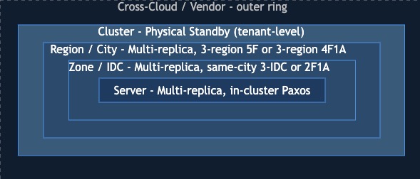
Each ring is a larger blast radius. Multi-replica Paxos contains the inner three by varying where replicas are placed via Locality. Physical standby is the only mechanism that crosses the cluster boundary. Cross-cloud / cross-vendor sits beyond cluster and is an operational discipline, not a single product feature.
Two patterns worth lifting out before reading the topology section:
- Arbitration-based recovery changes cost, not the failure-domain ladder. It is one of the three HA mechanisms from the first post, but it does not create a new blast-radius category.
2F1Aand4F1Akeep the same domain coverage as their full-replica counterparts while replacing one full replica with a lightweight arbiter that votes on elections and membership but not on log Accept. (See Arbitration service overview for more details.) - Only physical standby crosses the cluster boundary. Planned Switchover preserves RPO = 0. Unplanned Failover preserves RPO = 0 under synchronous standby modes; the default asynchronous mode loses lag-bounded data. A later post in this series covers the mechanics.
Where each replica actually lives - the per-tenant Locality declaration - is the subject of the next post. With the failure-domain map above in hand, the named topologies operators choose read straightforwardly.
Topology Choices by Failure Domain
Once the failure domain is clear, the topology list becomes much easier to read. Each option below is a different answer to the same design question: how large a failure can this deployment absorb before the application has to leave the primary cluster?
| Topology | Replicas | Best fit | Doesn't cover |
| Single IDC | 3F | RPO = 0 for single-node minority failure | IDC, Region |
| Same-city 3-IDC | 3F | RPO = 0 for single-IDC failure | City |
| Two-region 3-IDC | 5F (4 + 1) | RPO = 0 for single-IDC failure across two regions | Primary-city loss |
| Three-region 5-IDC | 5F (2 + 2 + 1) | RPO = 0 for minority-city failure | Total cluster loss |
| Same-city 2F1A | 2F + 1A (2 full IDCs + arbiter in a third) | RPO = 0 for single-IDC failure, at lower cost than 3F | City; total cluster loss |
| Two-region 4F1A | 4F + 1A (2F + 2F in primary city + 1A in secondary) | RPO = 0 for single-IDC failure, at lower cost than two-region 5F | Primary-city loss |
| Three-region 4F1A | 4F + 1A (2F + 2F + 1A across 3 cities) | RPO = 0 for minority-city failure, at lower cost than three-region 5F | Total cluster loss |
| (Any of the above) + physical standby | + standby tenant | Cross-cluster DR: RPO = 0 for planned Switchover; possible data loss for Failover | Synchronous zero-loss recovery from total primary-cluster loss |
Two points the table doesn't make loudly enough:
- Two-region/three-IDC is not city-level DR. It places four replicas in the primary city across two IDCs and one in the secondary city. Any single IDC failure leaves a majority alive - but losing the primary city loses four of five replicas, and the surviving replica is a minority. The name sounds like regional DR; the quorum math says it is still an IDC-failure design.
- The arbiter is a cost lever, not an availability lever. Each
nFnAtopology is the arbiter variant of annFfull-replica topology with the same blast-radius coverage, at lower cost: - same-city
2F1A↔ same-city 3F, - two-region
4F1A↔ two-region 5F, - three-region
4F1A↔ three-region 5F.
The third site (or fifth IDC) hosts a lightweight arbiter instead of a full replica. The arbiter doesn't change which failures the topology survives - it changes the price.
The three multi-IDC topologies look like this:
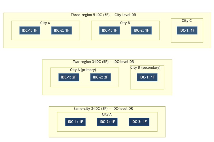
Same-city 3-IDC defends against IDC failure within a metro. Two-region/3-IDC defends against any single IDC but loses majority if the primary city goes down. Three-region/5-IDC is the only single-cluster layout that preserves RPO = 0 under a minority-city loss.
The topology table answers the first design question: "what is the largest failure domain I need to survive?" The decision matrix adds the second question: "what am I paying for that survival in latency, cost, and operational scope?"
The Disaster Recovery Decision Matrix
For an architect picking between these, the useful view is the trade-off plane:
| Criterion | Single IDC 3F | Same-city 3-IDC | Two-region 3-IDC | Three-region 5-IDC | Same-city 2F1A | Two-region 4F1A | Three-region 4F1A | + Physical Standby |
| Worst blast radius tolerated with RPO = 0 | Single node | Single IDC | Single IDC | Single city (minority) | Single IDC, at lower cost than same-city 3F | Single IDC, at lower cost than two-region 5F | Single city (minority), at lower cost than three-region 5F | Total primary-cluster loss, only via planned Switchover |
| Handles primary cluster loss | No | No | No | No | No | No | No | Yes, through Failover; data loss depends on sync progress |
| Typical RTO | < 8 s | < 8 s | < 8 s | < 8 s | < 8 s after downgrade | < 8 s after downgrade | < 8 s after downgrade | Seconds to minutes; decision-bounded |
| Write latency floor | LAN | Intra-city (see note) | Cross-region (see note) | Cross-region (see note) | Intra-city (see note) | Cross-region (see note) | Cross-region (see note) | Mode-dependent: async modes don't impact primary writes; sync modes add cross-cluster commit cost |
| Third-site cost | n/a | Full IDC | Full secondary-region replica | Full region | Cheap arbiter node | Cheap arbiter node | Cheap arbiter node | Separate cluster |
| Operational scope | 1 cluster | 1 cluster | 1 cluster | 1 cluster | 1 cluster | 1 cluster | 1 cluster | 2 clusters |
| Application visibility | Transparent | Transparent | Transparent | Transparent | Transparent | Transparent | Transparent | Transparent via obproxy auto-routing (4.2.4+) |
Latency-floor numbers above are intentionally qualitative pending product confirmation. Same-city IDC-to-IDC latency can be low, but cross-region latency depends on physical distance and the network route. Treat write-latency comparison as ordinal: each step right is a larger commit fan-out.
Left to right, the matrix is a sliding scale between cost and blast radius. Single-IDC 3F is cheap and fast and protects nothing larger than one machine. Two-region 3-IDC adds geographical distance but still protects against IDC failure, not primary-city loss. Three-region 5F is expensive and adds cross-region commit latency, but it is the only single-cluster posture that survives a city. The 2F1A and 4F1A columns are cost levers: they keep the same broad failure-domain target as their full-replica counterparts while replacing one full replica site with a lightweight arbiter. Physical standby is what you add when your blast radius is bigger than any single cluster, with the important caveat that planned Switchover and unplanned Failover have different RPO semantics.
Composing Layers - and the Cross-Cloud Outer Ring
Once the single-cluster choice is clear, the final question is whether the cluster boundary itself is part of the blast radius. Multi-replica DR and physical standby compose: a three-region 5F primary plus a physical standby tenant in a separate cluster is the canonical pattern when compliance requires an independent cluster, when DR spans clouds or vendors, or when a read-only tenant in a third site is useful for reporting.
OceanBase's built-in HA stops at the cluster boundary. The cross-cloud layer - log transport, network design, identity, data-movement tooling - is an operational discipline beyond any single cluster's HA mechanisms; Tenant-level switchover and failover mechanics are covered in a later post in this series.
The topologies above assume the classical shared-nothing architecture - each replica stores its own data and log. OceanBase's shared-storage architecture is a different design axis, not another row in the multi-replica DR ladder.
Anti-Patterns
A few mistakes show up often enough to call out:
- Treating two-region/three-IDC as city-level DR. It isn't. The documented capability is IDC-level inside the primary city, not survival of the primary city.
- Using physical standby for HA inside one region. Multi-replica handles that faster (synchronous, RPO = 0, RTO < 8 s) and cheaper. Physical standby's value is the cluster boundary, not the failure semantics.
- Picking three-region 5F for a workload that won't tolerate cross-region commit latency. Every write commits across cities. If the workload is latency-sensitive OLTP that can tolerate IDC failure but not city failure, a same-city 3-IDC or 2F1A topology is the right answer.
- Skipping arbitration in 2-IDC deployments. If the budget genuinely allows only two datacenters, a 2F1A topology is almost always better than paying for a full third-IDC replica or accepting only single-node availability.
What's Next
Choosing the topology is half the design. The other half is declaring it - describing replica counts, replica types, and Zone placement at the tenant level so the cluster actually arranges itself that way. That declaration is Locality, which we will dive deep in the next post.
Further reading:


Keep Reading
View all posts
From Complex to Simple: How We Built seekdb for the AI Era
AI era doesn't need another heavy, complex enterprise database. It needs agility. It needs flexibility. We went back to the drawing board to understand what an AI application actually needs from a database. Our answer is OceanBase seekdb


Beyond Fine-tuning: Solving DABstep's Hard Mode with Versioned Assets
On the DABstep Global Leaderboard, OceanBase DataPilot agent has secured the top spot, maintaining a significant lead over the runner-up for a month. The secret to our SOTA results was a fundamental shift in engineering paradigm: moving from "Prompt Engineering" to "Asset Engineering."

Permanent Server Offline in OceanBase: How the Cluster Heals After a Node Is Gone
How OceanBase distinguishes a transient outage from a permanent loss, and why operators should intervene rather than wait for the automatic re-replication timer.